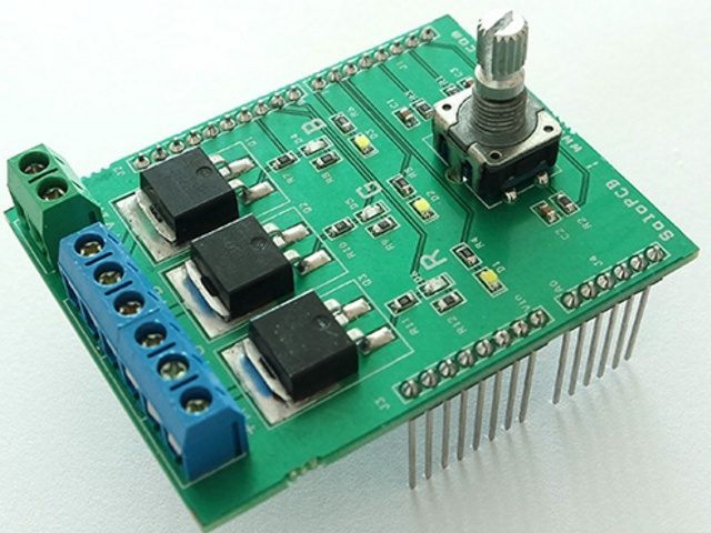
Controlling 4 RGB LEDs with arduino.
Repair Golovna.
We already tried it the previous lesson.
Now let’s look at the rich LED, which is often called for short:
RGB LED
RGB is an abbreviation that stands for: Red – red, Green – green, Blue – blue. So in the middle of this device there are three LED lights. Depending on the type, the RGB LED can be either a solar cathode or a solar anode.
Mix of quotes
Why is an RGB LED better than the other three? The whole river at the center of our vision is mixed with light from different dzherel, placed close to one another. For example, if we set a blue and red LED, then at the distance of several meters the light will turn green, and the eye will add one purple dot.
And if we add more greens, then the specks will turn out white to us.
This is how computer monitors, televisions and outdoor screens work.
The TV matrix consists of several points.
The analog output is a PWM controller, to which a signal with a frequency of approximately 500 Hz is supplied with adjustable frequency.
What is a PWM controller and the principle of its operation can be found on the Internet.
Through the analog port it is possible not only to switch on the voltage, but also to change the voltage (stroke) on it.
Command Syntax Digital icon:
pinMode(12, OUTPUT);- set port 12 as the data output port;
digitalWrite(12, HIGH);
- A logical unit is supplied to discrete output 12, lighting up the LED. Analog visnovok:
analogOutPin = 3;– set port 3 for outputting analog values;
analogWrite(3, value);
– a signal is formed at the output from a voltage of 0 to 5V.
Values – scale the signal from 0 to 255. At a value of 255, the maximum voltage. Methods for using LEDs via Arduino You can connect either a weak light-emitting diode directly through the port, or even through an interconnecting resistor.
Try to turn on the tension more tightly and you will see that everything is going well.
- For greater emphasis, including
- light-colored lines
- , Vikorist an electronic switch transistor.
| Types of transistor switches | ||
|---|---|---|
| Bipolar; | Poloviy; | Warehouse (Darlington Warehouse). |
 |  |  |
Connection methods Through a bipolar transistor Via a field transistor
Through a voltage switch
At the hour of submission of a high logical level
(digitalWrite(12, HIGH);)

through the output port to the base of the transistor through the collector-emitter lanyard, the reference voltage flows to the vantagen.
In this manner, you can turn on and off the LED. The field-effect transistor operates in a similar manner, except for the fragments of the “base” stack, which is fused not by force, but by voltage, and the interconnecting resistor in this circuit is not necessarily viscous. Bipolar vision does not allow you to regulate pressure.

The flow through new boundaries is less than 0.1-0.3A.
Field transistors operate with higher voltages up to 2A.

By connecting the transistor to the analog port of the Arduino, the value assigned to it is from 0 to 255, and the voltage supplied to the collector or drain is changed from 0 to 5V.
Through the collector-emitter lanyard we pass from 0 to 100% of the reference voltage.
To power the Arduino light strip, you need to select a voltage transistor.

The working flow for the life of a meter of LEDs is 300-500mA, for which a power bipolar transistor is suitable.
For great results you will need a field-effect transistor.
Connection diagram for LED strip to Arduino:

Controlling RGB stripes with Andurino help
 In addition to single-chip LEDs, Arduino can be used with color LEDs.
By connecting the skin color circuit to the analog outputs of the Arduino, you can significantly change the brightness of the skin crystal, achieving the desired color light. Connection diagram to Arduino RGB LED: The same RGB stripe was created using the Arduino strip:

Arduino RGB controller is better than using field-effect transistors.
For smooth keruvannya brightness You can use two buttons. One is the brighter brightness of the candle, the other is changeable.
Sketch showing the brightness of the Arduino LED strip
int led = 120; installable
middle rhubarb
brightness void setup() (
}
pinMode(4, OUTPUT);
we install the 4th analog port on the display
pinMode(2, INPUT);
pinMode(4, INPUT); we install the 2nd and 4th digital port on the input for button operation
{
void loop()
button1 = digitalRead(2);
}
button2 = digitalRead(4); if (button1 == HIGH)
{
Press the button to increase brightness
button1 = digitalRead(2);
}
led = led + 5;
analogWrite(4, led);
if (button2 == HIGH)
 Press the button on your friend to change brightness
led = led - 5;
When the first or other button is pressed, the voltage that is supplied to the remaining contact of the electronic key smoothly changes.
Then there will be a smooth change in brightness.
 Arduino modules
To create a full-fledged driver, sensor modules can be used with a LED strip.
IR control
The module allows you to program up to 20 commands.
 The signal radius is close to 8m.
The price for the set is 6 USD.
By radio channel
Four-channel block with a radius of up to 100 m.
: red, green and blue.
By simultaneously adjusting the brightness of three light-emitting diodes of the skin from these colors, you can create a light color of any color.
LEDs that allow you to change the color of the produced light, such as those shown in our final lesson, are controlled in a similar manner, but in their designs there are three different LEDs all at once in one very small building.
Such a warehouse triple light-emitting diode is called RGB LED.

Let's create a high-quality RGB LED using three adjacent 5mm LEDs.

These three light-emitting diodes shine through the clear, bar-free lenses, so we need light-emitting diodes with clear, bar-free lenses, and they can come in any color! If you choose another set, just find one red, one green and a blue LED (with a barless or pre-printed lens). Unplug the USB cable and replace the red LED with one of the clear lens LEDs, then reconnect the USB cable.
What color LED?
{
If you find a red one from the first test, add it and repeat the process to determine the color of two other LEDs.
Connect the other two LEDs with 1K resistors in series to pins 10 and 11, as shown in the diagram.
Download and open the code from the Tinkercad Circuits module, or copy and paste it into a new empty Arduino sketch.
}
Take it to your Arduino Uno board and marvel at how you can create rows of code with the steps that you run on LEDs, as it was done before. The unknown part of this code is the setColor() function;
.
Now, when a function is called in the main loop, the program writes the function code before continuing with the main loop.
In this case, the arguments are discussed as a code for the level of brightness of the skin with light-emitting diodes.
The range for setting brightness is 0-255, so for skin coloring one byte is used, which allows you to set 256 different levels of brightness.
Now download and open the code from this larger RGB project or copy and paste the code from a new empty Arduino sketch. Read the comments in the code to learn more about how the program works. The code works by mathematically calculating the transformation of the range 0-100 into the required range required by LEDs (0-255). This is straightforward, so you can think about brightness in cameras instead of the range 0-255. To save information about the color code, use the vikoryst set of changeable titles
Tsey is awkward

Arduino project


applications for caravanning using additional PWM (pulse width modulation).
In many applications, both amateur and professional, it may be necessary to generate colors of different colors.
The use of several single-color LEDs is not justified in terms of design and economy.
Therefore, RGB LEDs were provided for such purposes. RGB LED (the abbreviation means RED, GREEN, BLUE) is based on crystals that generate red, green and blue colors. Therefore, such a connected LED can produce 16 million light outputs.

It is not easy to install RGB LEDs, and they can be used in Arduino projects without any problems.
This material will show the use of an RGB LED using Arduino.
The fragments of the RGB LED, as it was designated above, are combined with crystals of three different basic colors, then circuit-wise they are displayed as three LEDs.


