A radio amateur kettle requires a variety of circuits.
Cooking
Lower induced complex light-sound circuits, mainly based on multivibrators, for radio amplifiers.
All vikoristan schemes have the simplest elemental base, no complicated setup is required, and it is possible to replace elements with similar ones over a wide range.
Electronic pumping The toy's pitching can be ensured by a clumsy "quack" simulator circuit on two transistors. The circuit is a classic multivibrator on two transistors, in one arm of which there is an acoustic capsule, and the other arm contains two LEDs that can be inserted into the eyes of a toy. Offenses and obsessions are carried out in a different way - either the sound is moonlit, or the light is shining - the eyes of the jocks. A reed switch sensor can be installed in the life supply tank SA1 (can be taken from sensors SMK-1, SMK-3 and others that are used in security alarm systems as door sensors).
When the magnet is brought close to the reed switch, the contacts close and the circuit begins to operate.
This can be done by placing the toy in front of the attached magnet or by presenting a charming stick with a magnet.
Transistors in the circuit can be either
p-n-p type
, low to medium tension, for example MP39 – MP42 (old type), KT 209, KT502, KT814, with a gain factor of over 50. Transistors can be used vicor
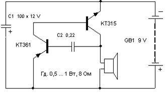
It is possible, for example, to sound a radio-coated or other model of a transfer device.

Options for replacing transistors and dynamics are the same as in the previous circuits.
Transformer T1 is the output from any small-sized radio receiver (through the receivers there are also speaker connections).

There are no schemes to imitate the sounds of birds singing, the voices of creatures, the whistle of a steam locomotive, etc.
The circuit shown below is based on one digital microcircuit K176LA7 (K561LA7, 564LA7) and allows you to suppress various sounds depending on the size of the support that is connected to the input contact ів Х1.
Please note that the microcircuit here operates without power supply, so that its positive pin (pin 14) is not supplied with voltage. If you want to actually install the microcircuits, it still works, but only when you connect the sensor support to the X1 contacts. Each of the eight inputs of microcircuits connects to the internal life bus through diodes that protect against static electricity or incorrect connection.
Through these internal inputs, the microcircuits are used to ensure the presence of a positive feedback loop through the input resistor-sensor.
The transistor can be replaced with KT3107L, KT361G, but in this case it is necessary to install R4 with a 3.3 kOhm support, otherwise the volume of the sound will change.
Capacitors and resistors - of any type with ratings close to those on the circuit.
Please be aware that in microcircuits of the K176 series of early releases, there are bad conditions every day and such examples in this scheme do not apply!
It is easy to verify the presence of internal diodes - simply measure with a tester the support between the displayed 14 microcircuits ("+" life) and the input circuits (or preferably one of the inputs).
As soon as the diodes are checked, the pressure in one direction is low, in the other – high.
Vimic life in this circuit can not be stagnated, because in the quiet mode the device produces a flow of less than 1 µA, which means less self-discharge of any battery!
Nalagodzhennya
Properly collected water simulator does not matter.

To change the tone of the sound, you can select capacitor C2 from 300 to 3000 pF and resistors R2, R3 from 50 to 470 kOhm.

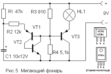
Lighter flasher
The frequency of the flashing lamp can be adjusted by selecting elements R1, R2, C1.
In contrast to the impersonality of the circuits of such automatic machines, they are distinguished by their borderline simplicity and reliability, and in report description I won't require it.

It allows lighting or electrical appliances to run for an uninterrupted hour, and then automatically turns them off.
To increase the intensity, press the SA1 device for a short time without fixing it. When this happens, the capacitor starts charging and turns on the transistor, which turns on the relay. The turn-on hour is determined by the capacitance of the capacitor with the nominal value indicated on the circuit (4700 mF) becoming close to 4 volts.
More than an hour of switching on will reach the connection of additional capacitors in parallel.
| The transistor can be either an n-p-n type of medium tension or a low-tension type KT315. | This should be kept in the operating line of the relay, which may also be different for the voltage required by 6-12 V and the existing switches will provide the necessary voltage for you. | You can vikorist and | pnp transistors | type, but it will be necessary to change the polarity of the supply voltage and turn on the capacitor C. Resistor R also flows in at short intervals per hour of use and can be rated 15...47 kOhm depending on the type of transistor. | List of radio elements | Appointment | |
|---|---|---|---|---|---|---|---|
| Lower induced complex light-sound circuits, mainly based on multivibrators, for radio amplifiers. | |||||||
| Type | Denomination | Quantity | 2 | Note | Shop | ||
| My notebook | VT1, VT2 | Bipolar transistor | 2 | Shop | |||
| KT361B | MP39-MP42, KT209, KT502, KT814 | 1 | Shop | ||||
| Before the notepad | HL1, HL2 | LED | 1 | Shop | |||
| AL307B | C1 | 100uF 10V | 2 | Shop | |||
| C2 | C1 | Capacitor | 1 | Shop | |||
| 0.1 µF | R1, R2 | Resistor | 1 | Shop | |||
| 100 com | R3 | 1 | Shop | ||||
| 620 Ohm | BF1 | Acoustic viprominyuvach | 1 | Shop | |||
| TM2 | |||||||
| Denomination | Quantity | 1 | Shop | ||||
| Denomination | SA1 | 1 | Shop | ||||
| KT361B | Reed switch | GB1 | 1 | Shop | |||
| Before the notepad | HL1, HL2 | Life element | 1 | Shop | |||
| 4.5-9V | A simulator of the sound of a metal ball bouncing. | 1 | Shop | ||||
| 620 Ohm | BF1 | KT315B | 1 | Shop | |||
| , low to medium tension, for example MP39 – MP42 (old type), KT 209, KT502, KT814, with a gain factor of over 50. Transistors can be used vicor | |||||||
| Denomination | SA1 | 1 | Shop | ||||
| Denomination | Quantity | 1 | Shop | ||||
| KT361B | Reed switch | Electrolytic capacitor | 1 | Shop | |||
| 100uF 12V | 0.22 µF | Dynamic head | 1 | Shop | |||
| GD 0.5 ... 1 Watt 8 Ohm | C1 | 9 Volt | 1 | Shop | |||
| 15uF 6V | R1 | 1 | Change resistor | Shop | |||
| 470 com | |||||||
| R2 | 24 com | T1 | 1 | Transformer | Shop | ||
| Denomination | Kind of like a small-sized radio receiver | 1 | Universal sound simulator | Shop | |||
| KT361B | HL1, HL2 | DD1 | 1 | Shop | |||
| Before the notepad | HL1, HL2 | Microcircuit | 1 | Shop | |||
| K176LA7 | C1 | K561LA7, 564LA7 | 1 | Shop | |||
| KT3107K | C1 | KT3107L, KT361G | 1 | Shop | |||
| 4.5-9V | 1 µF | 1 | Shop | ||||
| 620 Ohm | BF1 | Acoustic viprominyuvach | 1 | Shop | |||
| As soon as the diodes are checked, the pressure in one direction is low, in the other – high. | |||||||
| Type | Denomination | ||||||
1000 pF R1-R3

330 com The basics of digital electronics are presented in a simple and accessible way for beginners - the way to build copper and cognitive devices on transistors and microcircuits on a breadboard, which immediately after assembly begin to operate, without Magically soldered, designed and programmed.
Recruitment of necessary information details to a minimum, both for the cost of hiring and for the job.

During the hour, the presentation is given nourishment for self-verification and consolidation of the material, and encourages creativity in the independent development of schemes. Oscillography.
![]()
Basic principles of vimirs.

Oscilloscopes are an indispensable tool for those who design, manufacture or repair electronic equipment. In the current world, which is rapidly changing, the fakhivians need the best possible equipment for the rapid and accurate fulfillment of their daily needs, connected with the dying orders.

Being the "parent" of engineers in the world of electronics, oscillography is a key tool for internal processes in electronic circuits. It's easy to design and build a Tesla cat. For a beginner, you don’t need to use folding ones (most of the time it was folding), or you can remove the working coil, following the instructions in this article and making minor adjustments. Of course, if you want a very tight cat, there is no way except to follow the theory and carry out the treatment without swelling.

Self-talk of a young radio amateur.
The book describes sound simulators, connected electrical wiring, acoustic devices, automatic sound generator models, electric musical instruments, electric guitar attachments, color music attachments and other designs, Select from available parts
School radio station ShK-2 – Alekseev S.M.

The book consists of descriptions of simple structures that electronic components, and experiment with them.

In addition to traditional designs, whose robotic logic is determined by their own circuitry, we add a description of the components that are functionally implemented by additional programming. The theme of the games is electronic games and souvenirs. How to master radio electronics from scratch If you have a great desire to be friends with electronics, if you want to create your own ideas, but don’t know where to start, contact this teacher.

You'll learn how to read circuit diagrams, use a soldering iron, and make a lot of little tricks. You will learn to use the magical tool, rozrobljat and svoryuvat drukovani pay, you learn the secrets of many professional radio amateurs. With Zagal, you gain enough knowledge to further master electronics on your own.

Soldering is easy - pokrokova kerivnitstvo

for cobs. The comic, regardless of its format and obscurity, explains in detailed detail the basic principles of this process, which are not at all obvious to people who have never touched a soldering iron in their hands (as practice shows, for the rich who are also trim).

If you have long wanted to learn how to solder yourself or are planning to teach it to your children, then this comic is for you. Electronics for those who drink. This book was written especially for you as you begin your tumultuous journey to the heights of electronics.

This is another book from a series of videos addressed to the beginning radio-amator as a basic and practical guide. This book provides a more thorough understanding of various circuits based on the conductor and radio-vacuum base, the basics of sound engineering, electricity and radio-dimming. Wiklad is supported

great strength Illustrations and practical diagrams.
Radio operator's hat.
The main and only purpose of this book is to get to the radio amateur creativity of the boys, who do not worry about the process of waiting. The book is inspired by the principle “from the basics - through familiarity - to understanding” and can be recommended to middle and high school students as a guide to the beginnings of radio technology. For electronics nerds, it is important to understand how parts are arranged, how they are drawn on a diagram, and how to understand the electrical principles of a circuit.
To do this, you need to first become familiar with the principle of operation of elements, and how to read electronic circuits, I will recognize this information on the butts of popular devices for cobs.
Scheme

table lamp
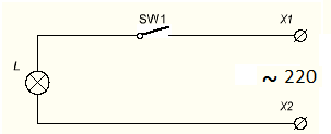
and light on LED
Scheme - the details of the circuit are displayed with the help of additional symbols, and their connections are shown with lines.
When the lines fray, there is no contact between these conductors, and if there is a point in the place of the fray, there is a connection between several conductors.
The number of icons and lines on the diagram shows the designation letters.
All indications are standardized, each country has its own standards, for example, in Russia they adhere to the GOST 2.710-81 standard.
Let's move on to the offensive scheme.

The whole battery is supplied with batteries, as it is installed in the new one.
Take a look at the diagram and you might get a new picture.
The right-handed one is depicted as a battery of life, this is how a battery or accumulator looks like, the long one is plus another name - Cathode, the short one is minus or Anode.
At the LED, a plus is connected to the anode (the three-piece part of the designation), and a minus is connected to the cathode (it looks like a blur on the UGO). It’s important to remember that the life of the villagers and the co-workers named the electrodes for the sake of it. The two arrows that come out of the LED will give you an idea that this device is changing the light, as the arrows seemed to indicate on the new photo taker.
The letters indicate the designation VDx, where x is the serial number.

Important:
Numbering of parts on

schemes go
with the beast's fists down to the bottom, towards the right.As soon as the stabilization system is added to the scheme, the voltage of the life block will be stabilized.
The connection with this is often due to nutrition, as you learn to read electrical diagrams, where all warehouses are displayed in the form of mental graphic symbols.
This problem is of great importance for those who regularly deal with electrical installations.
Correct reading of diagrams makes it possible to understand how the elements interact with each other and how all work processes take place.
See electrical diagrams In order to correctly draw electrical circuits, it is necessary to first become familiar with the basic concepts and implications of this area. Whatever the scheme looks like a graphic image or armchair, on which all the connecting arms of the electric stake are displayed at once.
Is scurrying
different views
electrical circuits that are separated for their own purposes.

On important diagrams, other elements that are subordinate to the main functions are not indicated. The structure of this image is simple, allowing us to better understand the principle of all possession. Installation diagrams, however, are drawn in more detail, the fragments of the stink are collected for practical installation of all elements
electrical lines
.
Before them, there are single-line diagrams that are displayed directly on the real-life plan of the facility, as well as diagrams of cable routes from transformer substations and other substations, plotted on the general plan. During the installation process, the creation of a wide range of circuits with secondary lances became possible. They show additional functional subgroups of lancets associated with inclusions and complications, individual protection of any plot or other.

Designations in electrical diagrams
- The skin electric lancus has devices, elements and details that all at once create ways for
- electric struma
- .
The stench is revealed by the presence of electromagnetic processes associated with electrodestructive force, flow and voltage, as described by physical laws.
Most lances are made up of various electrical devices that are subject to different operating modes, depending on the current and voltage values.

In idle mode, there is no flow into the lancet. Sometimes such situations arise when the situation breaks down. In the nominal mode, all elements operate with force, tension and tension, as indicated in the device passport.
All storage and intelligent components of the electric lancet are displayed graphically.

On the little ones you can see that the skin element and the attachment are indicated by their mental icon.
- For example, electrical machines can be represented in a simple or open way.
- It is obvious that there will be smart graphic schemes. To show the main windings, single-line and multi-line images are used. The number of lines must lie in the number of strands that will be different in
- Melting fuses, resistors, capacitors.
- Each of them is represented by icons.
- Swimming trunks are depicted as a rectilinear with inlets.
For constant resistors, the icon may have leads or leads.
The contact contact of the exchange resistor is indicated by arrows.

The small capacitors display a constant and variable capacity. See the picture for polar and non-polar electrolytic capacitors. Air supply devices. The simplest ones are the one with a p-n junction and one-way conduction. Therefore, the stench appears at the sight of the tricut and the line of the electrical connection that binds it.
It is much easier to work with components represented by transistors, triacs, microcircuits, etc.

The folding design of such elements conveys a more complex display of them on electrical circuits.
For example, a skin bipolar transistor has at least three connections - base, collector and emitter. Also, our mental image requires special graphic mental signs. This helps to distinguish among themselves the details with individual basic powers and characteristics.
The skin of the mind is designed to take revenge on itself with encrypted information. For example, bipolar transistors may have a different structure - p-p-p or p-p-p, so the images on the diagrams are also noticeably different. It is recommended that you become familiar with all the elements before reading the electrical diagram principles.
The details of the image are often supplemented with additional information.
If you look carefully, you can see the Latin letters symbols on the skin.
- This rank signifies this other detail.
- This is important to know, especially if you only want to read electrical diagrams.
- Bіlіternykh vyznanie rastashovanny y digits.
- Please indicate the following numbering or
- technical characteristics
- elements.
- You can make simple electronic circuits with your own hands for Wi-Fi in everyday life without any in-depth knowledge of electronics.
In fact, in everyday life, radio is very simple. Knowledge of the elementary laws of electrical engineering (Ohm, Kirchhoff), sacred principles

Robots of power supply devices, the ability to read circuits, and the ability to work with an electric soldering iron are enough to assemble the simplest circuit.
Radioamator workshop
Call for more literature from galusi electronics for radio amplifiers. classic stock preparation of the simplest preparations.
Particularly valuable is the classic old literature, where there are many principled pardons against everyday life. Increase your respect!
These schemes were developed based on the great intensity of the radio stations that are broadcast at the last hour.
Today's transmission centers have less pressure for transmission and are designed to operate within a range of short lengths.
It’s not worth spending an hour trying to make a working radio receiver using the simplest circuit. Radio circuits for innocent mothers have a maximum of two or three active elements in their warehouse - transistors.
- This will make it easier to learn robotic schemes and increase your knowledge.
- What can you earn?
- What can be done that is both simple and practical and can be practiced at home? There are a number of options: Apartment jingle;

Remixing Yalinka garlands; Subswitching for modding
system unit computer. Important!
Do not construct devices that operate as a daily basis for changing the flow until there is insufficient evidence.
This is not safe both for life and for those who live abroad.
The power supply of computer speakers and computers are built on specialized integrated circuits. Devices, collected on their basis, revenge minimum strength
elements and practically do not require regulation.

It is often possible to simplify circuits, which will require basic modifications, refinement, which will simplify preparation and adjustment.
It is up to the master to work on this development so that the pouch option is available to newcomers.
Highly qualified radio amators can themselves develop small wire-based circuit boards and print them on foil material, on which the radio elements can then be soldered.
The structure has been fragmented in this way to achieve optimal dimensions.
Design of the finished structure

Admiring the creations of the cobblers and advanced masters, one can realize that the construction and regulation of the device is not always the most difficult in the design process.
Sometimes a properly functioning device is deprived of a set of parts with wires that are soldered and not covered with any housing.
