Pressure switch for square antennas.
Hedgehog
The channel "Radio channel with Oleksii Igonin" talks about the antenna switch that you made with your own hands.
It is necessary to connect two antennas to such a number of radio stations, changing the location.
What is this needed for? If you have two radio stations that operate on the short wavelength range. One on the Chergovy Canal.
A high-speed antenna for one band is connected.
Otherwise, you may need a wide-angle antenna for monitoring or searching.
It does not matter which station you are on, whether you are looking for a signal or not.
Or why stand on the click frequency?
The aluminum box, crushed at the back, became useful for this one. This model does not have any vintage novelty, but at least similar devices
.

It is valuable that the research master has selected the best option and shown it on video.
The design is simple, there is nothing special to show.
The primary switch switches two inputs from two outputs.
In the first position, transceiver 1 connects to Antenna 1, transceiver 2 - to 2. For the other, transceiver 1 connects to antenna 2, and transceiver 2 - to 1.
We checked our switch on the 28 MHz HF band and on the 145 MHz UHF band.
KSV is not marked on special ranges, which means that it can be used on all ranges. And at VHF 2 meters the increase in SWR is approximately 0.1.
Marvel at yourself when you come to sign up.
The power didn’t go anywhere, but in the range of 70 cm and above, without becoming victorious about such a design of the switch. November 23, 2011
I.Є.
Kalashnikov (ux7mx).
ANTENNA SWITCH ON RELAY P1D-1V.
For a long time we didn’t get around to the antenna switch. If there were two antennas,
there were no problems, even with the transceivertwo roses. If you install 4 antennas,
I got tired of twisting the sockets, connecting first one antenna, then another.
The food has arrived,What should I work on and in what way and for what kind of effort?
There is still no RESPONSE, you can visconati
on basic ceramic biscuits type 11P1N or similar ones. Doctors who showed up with so many antennas on one The problem is in their training, they had to spend many hours on the best nutrition.
Positive results were achieved through the path of grounding
not working antennas.
To mean
the antenna switch needs to transfer capacitysuch commutation.
What is this radio station, as written on the label attached to the box. Yogo size250x105x50mm.
The storekeeper knows another box of treasures, I know UKH equipment, 115x100x30mm. As a result, I came up with the idea of building a switch based on a relay,
when serving food on one of them, on the P1D-1V bark, placed in a box, and intermittent
contact є,and begin to use 9-10 volts. And it's 13.8 volts,
no problem, tse The voltage can be taken from the transceiver power supply. I'm at the top,
having twisted
transceiver,
and all antennas are grounded, thus turning off the ability for the “forgetful”
Individuals burn the transceiver during a thunderstorm.
With robot 100 watts, voltage 13.8 volts,
taken from the power supply or from the transceiver, sufficient for a robotic relay, in which case a flow relay is used
40-45 ma.
When working under greater pressure, it is necessary to increase the voltage of the relay to
24-27 volts (data sheet on the relay), to ensure reliable contact during switching.
The voltage is 24-27 volts, you can take it from ROZUM, if you show up, it’s true
The idea is to install a power supply for the relay in the switchboard, if you don’t know the required dimensions of the transformer. And of course, do not overmix the antenna when transmitting!
A similar switch operates in my friend’s third circuit, output stage on GU-43B, and nothing!
Inserting 4 pcs. relay,
Feed-through capacitors, 4 pcs. HF discord
SO-239 and one CP50, ham production,
so on 80m the antenna is powered by RK-50,cable diameter 16mm.I really don’t know
This cable has a SO-239 connector. Soldered with a 2mm wire, the relay and HF are separated by the shortest
way, relay windings shunting with diodes and capacities 0.068, installing a 75k 2W resistor to remove static,
that's all covered with a lid,
a completely screened structure emerged.
When this structure is inserted into
larger box, like the R-381, in this order
The Ameritron RCS-4X antenna switch consists of two units - a fiber-protected switching unit that is mounted on your desk or an antenna and a ceramic unit located on your work station.

You can use a switch to mix HF antennas, with an SWR of no more than 1.1 in the frequency range 1.8-30 MHz.
The maximum pressure that can be supplied is 1500 PEP watts per kW.
To protect the HF guidance and transfer the code to the receiving TB housing, the control unit is connected to the metal.
The front panel of the unit is coated with Lexan polymer material, which is resistant to stains and allows for easy application of designated antennas.
The switch operates in conjunction with a 220 volt power supply through an adapter that is included with your kit.
Control operates via a coaxial cable.
The switching voltage is no more than 14 volts, which will ensure electrical safety when the external switching unit is installed, connected and in operation.
Technical characteristics -
Number of switched antennas: 4
Attenuation at 30 MHz: less than 0.05 dB
SWR: slightly more than 1.1 at frequencies 1.8-30 MHz
Hvilovyi oper: 50 Ohm


Maximum voltage that can be supplied: 1000 watts PEP per HF (intermittent under voltage is blocked)

Intermittent hour: 50 ms.
The control module (Fig. 1) of collections on a micro-folding unit K04KP020, which is installed in the control units (SVP4-10) of color TVs 3USTST, 4USTST.
The control of the microfolder operates via inputs X1-X6, indication signals are received from outputs Y1 - Y6, and control of the switch is implemented via outputs Y7 -Y12.
You can select outputs Y13–Y18 (not shown in the diagram), but remember that the “on” output potential drops from 12 to 0.2 Volts.
Output Y20 is used for audio signaling at the moment of pressing one of the buttons SB1 - SB6, or at the moment of switching to another antenna.
To signal stagnation, use the internal generator KPE-240, which is installed for sound signaling in uninterrupted living units and other devices.
Microassembly K04KP020 has a richly stable trigger and a set of electronic keys connected to all outputs.

At the moment the life trigger is turned on, the state is set if the outputs Y1, Y 7, Y13 are open.

When the REN33 relay is used, the voltage is higher than the rated winding and it heats up significantly, which is unnecessary.
Therefore, the relay of the switching module REN33 is switched on through a “forcing” lance, which consists of two resistors connected in parallel, with a voltage of 2 W and an electrolytic capacitor of 1000 μF.
The relay is switched on with a “forced” voltage of 24 V, which then decreases to a voltage of 12...14 V sufficient to power the relay. In this mode, the relay can remain in the switched-on state for a long hour without significant heating of the winding.


The relay contacts of the switching module are connected in such a way that, due to the absence of voltage on the relay windings, the antennas are closed, the antenna is grounded.
The cable module and cable switching module (Fig. 4).
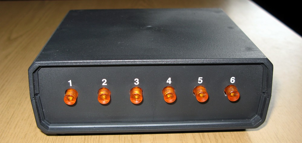
Finally, here are some photos of the finished antenna switch: Caravan unit, front panel::

Keruvanya block,

back panel

Control unit, middle:


Switching block, external appearance:
73!Switching block, middle:
Sergiy Nedilko UT3RS
- The idea of the need to prepare a clear antenna switch made me think about the instructions of my colleagues.
- In connection with this, having ruined the Internet, I ended up with the fact that the actual conclusions of the final decisions (including photographs) did not appear.
- Discussions on the forums gave the singer clarity about other aspects, otherwise he had to figure it out on his own.
- The following diet was required:
- Reliability
Introducing minimal inconveniences to the AFU path
- Flexibility of configuration, hundreds of changes that can be changed in HAM radio


Vandal resistance
Aesthetic modern look
Main and road power supply – select relay.
Regardless of the reliability of various viruses for the auto industry, I decided to rely on all types of life and selected 10 pieces of relay B-1-B (tnx RV9CPA).
7 of them went to the main thread and 3 went to the other.

The work with the “cowbass” with the purchase of cables and wires was as follows:
I live on the 1st floor in a 9-overhead booth, and the switchboard is responsible for standing still.
You can see the length of the cable harness - 60m!
And in the new one they entered:
Main feeder RFS ½’
Trunk feeder SAT-50 for another radio (optional, whenever you show up)
SAT-50 cable for TV antenna
Cable SAT-50 for UKH antenna X-300
Grounding cable 16 sq.
Cable keruvannya rotary attachments YAESU
- “Polivka” P-274 for supplying power to the 220V electrical outlet that is installed in the switch.
3 twists of UTP-5 pairs for switching relays and other needs
Well, it’s solid... It was decided to put everything in a 52mm metal sleeve.

It turned out that such a diameter is above ground, and the maximum drill to a hammer drill has a diameter of 40 mm.
In fact, it’s already a very professional technique and the opening at the wall has become a “gold” for spending money on a new one.
Rumors about the 38mm metal hose “shuddered” led to the understanding that such a product is a rare item (not a “hot” product) and, moreover, cannot be sold in one piece of 60m.

And it was impossible to find three pieces of 20m each, but it was now necessary to work.

Next, it was necessary to drill a 500mm hole at the wall of the balcony to insert the metal hose.
For this purpose we rented a professional hammer drill and 40mm SDS-max drill.
A rotary hammer drill is not suitable for this.
The completion was the fastening of the harness in a metal hose along the walls, which was installed in 4 places on plumbing clamps with gum gaskets - for the uncomplicated development of the entire structure.
The power clamps were not carried vertically.
Well, the most important part is complete.

Next is the insertion of the bundle into the switch body, already mounted on the wall of the elevator equipment room, and processing of the cable ends.
The axis looks like this:
- Switch for "working place"
- I won’t dwell on the finer points of the editing and editing – in the photo it’s almost clearer.
- The idea of the need to prepare a clear antenna switch made me think about the instructions of my colleagues.
- I am very concerned about the need to seal the place where the harness is inserted into the switch housing.
- It is also necessary to pay attention to the practicality of processing UTP cables - in the switch they are routed to the KRONE board, and in the sixth I connected them to the coupling and soldered the DB-25 connector in the middle, which will then have to connect to the control panel I'm using the switch.
Tobto.
Well, give a shout to the corps!
I desperately wanted something more metal that would allow the structure to be screened, but there was nothing obvious, and after thinking about it, this idea no longer became a priority - we bought a plastic case from some non-name transmitter for 300 rubles. The addition of the required PSW-22 buttons, the required color, and even without fixation, at that time turned out to be an unrealistic task - the place no longer had them, and when they were found, they were single copies. Here my friend RA 3ATX helped me - a pack of 24 buttons was delivered by mail and the layout of the front panel immediately began.
Due to the fact that I planned the split function, the number of buttons doubled, which was somewhat depressing, because... The front panel of the assembled body is no longer small enough to accommodate, due to the need to place switches and any additional switches on it. The placement of the buttons was modeled and the image file was sent to

e-mail RV 9 CTD

– Andriy helped to cut a bunch of squares on the front panel for the buttons on the laser machine, saving me a lot of effort, time and nerves.

After removing the panel, the buttons were firmly inserted - I couldn’t wait to see what it looked like.
Getting ahead of myself, I’ll say that it was early, because...
 It was necessary to drill a number of other openings in the panel.
Alya really wanted to
- J
- The panel remained like this for two years - until I received a new layer and I started making the remote control again.
- I’m omitting the soldering process, I’ll also point out that the external controls before the board were attached to the sockets of the manual connection from the body to allow for the necessary reconfigurations.
- The front panel was soldered straight away:
- A super-manual antenna re-mitter for another main line has been installed
- A three-position toggle switch has been installed for external primary antennas (incoming-incoming-outgoing)
- Locking buttons and antenna mixing in TX mode
- Control of two YAESU rotary devices (G800 and G1000) using one remote control and one cable.
When the 40-2CD antenna at 7 MHz is turned on, the PEM-22 relay is located in the middle of the switch, transferring the control cable to the G-1000.
The uninstalled cable has permanent connections up to G-800 and A3S.
Vlasna, the remote control diagram is shown below: Remote control diagram (press to enlarge) I don’t worry about the vitality of life and schemes, because...
The skin designer may have its own options. A bunch of relays in the remote control are silent, like 12V bulbs great quantity
(Tnx RZ9CX). Before speaking, the relays were simply glued together with double-sided tape, after which the entire briquette of 16 relays was glued with the same tape until payment. Depending on the type of relay selected, it is recommended to bypass the skin winding with a diode (VD25-VD39 on the attached circuit), and then correct the control transistors.
The upper microcircuit has only 7 ports, because
a total of 7 antennas for transmission.

- #1
All 8 ports will be stuck on the lower microcircuit, because
- #2
An additional relay with a socket is installed for auxiliary
- #3
prime antennas
- #4
directly in the commutator and can compete in the “split” mode.
- #5
Revert to connecting the buttons of the main node (IC1).
- #6
Because
- #7
when the remote control is turned on, it will be woken up first (automatically switched on)
port No. 1, on which the antenna is connected, which is most often used (A3S, in my opinion).
keruvannya with twists and turns?
Dovzhina not - #8
small, how about the tension?
- #9
I won't tell you the exact brand.
Ale Vi maєte raciyu - the summary summary is good)).
Alive, in my opinion, the skin is 0.75 mm2. - #10
- having grouped 4 pieces in parallel - having separated 4 pieces, they lived.
As a “minus” - all the braids are welded together.
- #11
Dmitry, I would still play it safe with diodes in parallel with the winding, there would be fire episodes and more oak transistors.
- #12
And give the opportunity to visualize the switch circuit separately, and not just look at it in a different way, which is not easy for those who want to repeat it.
- #13
Good luck!
- #14
>there were episodes of fire and more oak >transistors
- #15
Also, we are aware of the episodes of rapt fire of these diods)) OK, Mikhail, in response to your complaint, I’ll make an adjustment to the description and attach the diagram to a file. (Thank you for respect!)
73!
Let me tell you, the “pure black” color would be better than the transceiver, but everything is super!
- #16
Kostya, I’m good for you, especially since the computer cases are all black already))
I would like to express your respect for the TRA-2-L-S-Z relay from TIANBO, 24 volts. The mode of robotic contacts is via a changeable circuit 250V 16A. Not expensive 42 rubles. Very well suited for antenna switching references. - #17
And if the signal from the band decoder is connected to the V1 base with fewer keys, the band decoder itself is built on the PIC to implement the idea of a universal decoder from Icom
- #18
dead
